
Safety procedures, methods and designs are not novel concepts for the industrial manufacturing sector. In fact, layers of protection were put in place to protect personnel in manufacturing facilities dating back to the industrial revolution. As safety requirements and awareness evolved, larger corporations created their own safety standards to follow in house as “good engineering practice”. As you can imagine, this led to a cornucopia of different types of safety designs and standards by organization and by country. Couple that with governmental oversight bodies creating their own safety standards and you have an endless number of possibilities for risk mitigation and protection.
Fortunately, after years of committees, working groups, standards revisions and assimilation, global industrial process and manufacturing companies have predominately adopted and settled on a common safety standard: IEC 61511 Functional Safety – Safety Instrumented Systems for the Process Industry Sector. The foundation of this standard is that it recommends the use of a functional safety lifecycle and provides guidance on the actual implementation of safety instrumented systems for the process industry. This lifecycle guidance provides details on the analysis, design, operation and even decommissioning of the safety system by the organization. And of course, implementation of IEC 61511 cannot be accomplished without referencing the parent standard IEC 61508: Functional Safety of Electrical/Electronic/Programmable Electronic Safety-related Systems.
At the heart of the IEC 61511 standard is the SIS or Safety Instrumented System which is implemented to mitigate and prevent unacceptable risk by an organization to protect its personnel, facility and/or surrounding community and environment. Each SIS is made up of one or more SIFs, or Safety Instrumented Functions that bring a process or loop to a desired safe state. The basic elements of a SIF are the sensor, logic solver and final element. The sensor monitors the process and transmits that information to a logic solver where in turn that data is compared against predetermined settings to determine whether the final element should be adjusted, activated or engaged (Figure 1 (above)).
Since Logic Solvers are at the epicenter of every SIS decision, this white paper will primarily focus on logic solver capabilities and considerations. Currently, there are several vendors offering Functional Safety logic solvers, but there can be a large price and functionality gap that exists between single loop logic solvers and larger safety systems.

Figure 2. Logic solvers come in
different shapes and sizes but
vary greatly in cost, functionality
and complexity.
The key considerations, capabilities and features that should be part of the decision process in selecting a suitable logic solver for your Functional Safety application will be discussed and reviewed in the following sections. In addition, we will introduce the concept of the multichannel and multiloop logic solver that effectively fills the large price and functionality gap between single loop logic solvers and safety PLCs or larger safety systems.
The Logic Solver Gap
Of the three main components typically contained in the SIF, the logic solver is the most critical. The logic solver is responsible for making the determination of whether dangerous conditions have been met and is responsible for the final element’s ultimate effect on the mitigation function or strategy.
Two types of products have become widely accepted tools in implementing the logic solver component in Functional Safety applications. They are the Programmable Logic Controller, or Safety PLC, and the Single Loop Logic Solver. The Safety PLC, which is the generic name given to larger point count logic solvers, offers much more flexibility but does so at a significantly higher price and with greater complexity, while the Single Loop Logic Solver is more limited in its capability but can adequately reduce risks and meet safety system requirements with less expense and complexity.
Safety PLCs certainly fill key requirements within Functional Safety. Large point and loop counts, TMR (Triple Modular Redundant) applications or where the need exists to sync or network multiple safety logic solvers together in order to address a complex safety function. Safety PLCs are very capable but come with an extremely high price tag and often require sophisticated programming, maintenance and documentation.

Figure 3. The multiloop Logic
Solver with logic functionality and
voting capability can be an ideal
solution when Safety PLCs are
overkill but simple single loop logic
solvers fall short.
Conversely, there is the fully capable but smaller Single Loop Logic Solver that handles one loop and just a few points. Like Safety PLCs these are often IEC 61508 certified but have a much smaller footprint and cost far less than Safety PLCs. Additionally, the programming is less complicated and does not require any software licensing.
This is where the logic solver gap lies– functionality, complexity, and cost between these two types of logic solver options are vast (Figure 2). While each certainly has its place, there are many Functional Safety applications that require just two loops, or three loops with six inputs and six outputs and perhaps some simple 1oo2 or 2oo3 voting or math. The Safety PLC could certainly handle this, but is it overkill? Alternatively, Single Loop Logic solvers might be able to handle this with output relay wiring for voting, but point counts are limited and voting architectures can become convoluted with relay inter-wiring.
What is needed to fill this gap is a less expensive, less complex, multipoint, voting capable and IEC 61508 certified logic solver that allows safety practitioners an option that meets the functionality below that of the Safety PLC but above the capabilities of the Single Loop Logic Solver. Recently the marketplace has borne a few multichannel and multiloop logic solvers that fall squarely into this gap. These midsize certified logic solvers offer plenty of capability with smaller point counts and far less programming overhead.
SIF Logic Solver Selection
Safety Instrumented Functions (SIF) are designed to achieve or maintain a safe state with respect to a specific hazardous event within a process. Each SIF provides a defined level of risk reduction represented by its Safety Integrity Level (SIL), with SIL 4 having the highest level of safety integrity and SIL 1 the lowest. Any device used in the SIF for a specific SIL level requirement must be properly evaluated to ensure that it has the suitable proven in use history or calculated safety data such as failures and rates, Safety Failure Fraction (SFF), Probability of Failure on Demand (PFDavg), Systematic Capability (SC), etc. associated with it, typically outlined in the equipment manufacturer’s Failure Modes Effects and Diagnostic Analysis (FMEDA) report or safety certificate.

Figure 4. Ease of programming
with FDT/DTM for advanced
functions like 2oo3 voting
architectures don’t necessitate
complex programming or ladder
logic in modifications.
The selection of a logic solver in a SIF most often falls into one of three categories: device chosen due to proven in use history (individual components or whole device itself), device comes with published failure data such as a FMEDA report from the manufacturer, or device was manufactured in full compliance with IEC 61508 and has third party approval, along with accompanying FMEDA report and certificate.
While proven in use data is certainly an acceptable means of documenting a device’s capability and effectiveness to assist in a SIF, end users often find it extremely difficult or next to impossible to put their hands on such historical performance per device, especially for logic solvers. Utilizing failure data from the manufacturer’s report is certainly less burdensome, but for Type B devices which include most currently available logic solvers, this failure data does not cover the unknown systemic failures that can occur within software/firmware. Therefore, most safety practitioners have more confidence in and find it much more cost-effective to acquire products that were designed and manufactured in compliance with the IEC 61508 standard and have third-party approval. In addition, safety devices that are fully compliant with IEC 61508 further address and resolve systematic faults of the device through a full assessment of fault avoidance and fault control measures during hardware and software development.
The Price vs Capability Matrix
As mentioned prior and illustrated in Figure 2, the pricing and capabilities for different types of logic solvers can vary widely. This not only pertains to the initial expense of purchase, but also for the implementation of and life cycle costs in maintenance and programming. The most common determining factors in choosing which logic solver best fits a safety application are loop and point counts, communication requirements, and the complexity of logic required for safety mitigation.

Figure 5. Standalone logic
solvers often employ easy to use
and prebuilt programming and
logic functions.
When dealing with high density point and loop counts in a centralized location where there is interdependency on various points and loops, a larger more complex logic solver such as a safety PLC may be the best choice. Larger systems like these more easily afford themselves to more complex control logic and voting schemes with high reliability across a multitude of loops with several points. If points are not centralized, many of these larger safety systems can be networked together for flexibility in crosscommunication, as well as for future expansion. The tradeoff is that the initial costs of purchase, programming, and installation for a larger safety system or PLC can be very expensive— twenty-five thousand dollars or much more, not to mention the high lifecycle costs. Most larger safety systems often require programming modifications by a highly trained and skilled safety system programmer.
For scenarios where only one or a few points need to be monitored in a single SIF loop, a much less expensive and complex Single Loop Logic Solver can be a very effective choice. An example for this type of application would be simple on/off functionality for pump/valve control when filling, emptying, or preventing overflow in a container or tank. In fact, Single Loop Logic Solvers, also known as Alarm Trips, have made significant strides in their capabilities since they were first installed in SIS applications. These advanced capabilities include programmable inputs, local configuration using on-board controls, safe password protection, process display and comprehensive internal, input and sensor diagnostics. Single Loop Logic Solver output relays can also be wired in series to provide voting architectures but that requires extra field wiring and comprehensive wiring schematics. And while that may not be an overly complex task, if the voting logic changes meticulous rewiring of relays and rewriting of proof test procedures will follow. Standalone Single Loop Logic Solvers are of course less expensive and easy to program but are quite limited in their ability to handle multiple loops, accept multiple inputs, perform logic or internal voting, or provide digital communication with a BPCS (Basic Process Control System) or host system.

Figure 6. Configuration screens
with combo boxes and pull-down
menus allow for easy setup and
programming.
In the wide space that exists for applications that require higher density loop/point counts with more advanced logic and loop monitoring of only a few points, a Multiloop Logic Solver may be a more effective and better sized fit for many SIFs (Figure 3). Like the larger safety systems and PLCs, the standalone Multiloop Safety Logic Solver can accept multiple I/O points, handle one to three loops, performs logic and math equations, and offers significant flexibility for voting architectures at a fraction of the cost and complexity of larger safety systems and PLCs. Multiloop Logic Solvers typically harness the cost and configuration simplicity of Single Loop Logic Solvers, but also offer much of the advanced functionality of the larger safety systems and PLCs, albeit at smaller loop and point counts. These hybrid logic solvers can potentially meet many of the SIS applications that once required safety PLCs, but also offer an advancement in functionality and capability at an attractive price point for those smaller SIF loops that utilized Single Loop Logic Solvers.
Programming Cost and Ease-of-Use
Another consideration when selecting a logic solver is whether you need to purchase custom or licensed software and how easily it can be programmed to meet your SIS requirements. Many safety PLCs and larger safety systems offer their own proprietary software but often come with lofty initial price tags, annual licensing requirements or both. Alternatively, today’s marketplace includes very capable single and multiloop logic solvers with license-free and powerful programming software, including FDT (Field Device Technology) compliant interfaces.
The rigor of programming and long-term maintenance should always be a key consideration when choosing a suitable logic solver. As addressed earlier, large safety systems and safety PLCs offer significant flexibility but also come with a fair amount of complexity. To implement logic routines in these safety systems will require someone with significant knowledge of the programming language being used, whether it be ladder logic, function block diagram or structured text. This creates the need for programming expertise and adds additional time and expense to day-to-day operations and long-term maintenance of your safety solution. The litmus test may be to examine how long would it take to reprogram your current 1oo3 voting safety function to a 2oo3 voting scheme? If it takes someone that is not familiar with the logic solver software more than five minutes you may want to reconsider your logic solver choice, especially for such a straightforward application (Figure 4).
Depending on the requirements of your safety system, single or multiloop logic solvers usually offer much more straightforward programming options with easy-to-understand drop-down menus, check boxes, radio buttons, pre-built common control functions and math equation generation utilizing Excel-like formulas. While these smaller logic solvers are not quite as elaborate and may be limited on their I/O count, you may be surprised to find out how powerful but easy to program these logic solvers have become (Figure 5 & 6).
Figure 7. Logic solvers with
embedded read-only webpages
offer a valuable way to view and
share SIF status via off the shelf
web browsers.
Open Communication and Protocol Support
With the growing need for SIS logic solvers to communicate with a BPCS and higherlevel monitoring systems, the ability to communicate via open and widely supported protocols is paramount. Proprietary communication protocols may offer tighter integration when equipment is designed and manufactured by the same supplier, but seldom are the SIS logic solver and basic process control systems available from the same company.
Just as HART has become the de-facto digital communication method for lower (or floor) level field devices, many major industrial instrumentation and automation equipment vendors offer MODBUS as their preferred protocol for communication with ancillary control and monitoring systems. Like HART, MODBUS is the most ubiquitous and open industrial communication protocol that can run over virtually all communication media including twisted pair wires, wireless, fiber optics, Ethernet, cellular and satellite networks.
MODBUS/TCP, MODBUS RTU and several other proprietary industrial communication protocols support read and write commands. However, since logic solvers are typically the last line of defense, safety practitioners should strongly review whether allowing write access to the logic solver from a remotely connected host, or potentially unauthorized device is warranted or safe. If remote communication is required, consider choosing a logic solver that allows just “read-only” access over the industrial protocol. This still allows access to the logic solver’s process data and internal variables but prevents unauthorized access to setpoints, outputs and other critical safety parameters.
Some newer logic solvers may provide access to variables and other key parameters via a simple web browser, which can be a convenient feature (Figure 7). However, when using a web browser to access a logic solver, it is extremely important that the logic solver’s embedded web server serves up read-only data. This eliminates unwarranted changes being made to the logic solver’s safety parameters and variables.
If you require or prefer to have remote communication with your logic solver, make certain proper precautions are taken to prevent unauthorized or rogue access.
Cybersecurity Considerations
As referenced in the previous section, choosing a logic solver that has the ability to communicate efficiently with remote hosts or a Basic Process Control System is a common requirement. Determine whether a serial or Ethernet communication strategy is required for your safety applications. Taking advantage of interconnecting methods and strategies by utilizing a logic solver’s ability to communicate to higher level systems can create data analysis and archiving opportunities which can improve overall safety and assist with any safety audits. That said, precautions must be taken to minimize or even eliminate cybersecurity threats, especially when implementing Safety Instrumented Systems.
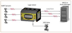
Figure 8. Some Logic Solvers
have the ability to pass along
critical HART process and
diagnostic data from safety
sensors to an auxiliary asset
manager or basic process control
system.
While serial networks aren’t necessarily as vulnerable to cyber-attacks from outside the facility, it is more important than ever that Ethernet-based logic solvers include safeguards within their products to ensure that network bandwidth is protected, viruses or malware cannot be loaded, unapproved reconfiguration of the logic solver is not allowed and unauthorized changes to safety parameters are not accepted by the logic solver. When reviewing the logic solver’s external digital communication capabilities, ensure the unit has the ability to disable all unwarranted programming or changes to critical safety parameters. Often this is accomplished with the use of physical solderless jumpers or switches that effectively air-gap the communication lines to certain areas of the logic solver from the digital communication link. Temporary remote programming may be necessary but a well-designed logic solver will offer continuous read-only access to key parameters but will include an ironclad way of preventing unauthorized access.
Utilize HART Diagnostic Data
A strong consideration in making sensor selections for your SIF is choosing transmitters (pressure, level, flow, temperature, etc.) that offer the greatest measurement accuracy and repeatability as possible. Most likely transmitters that fit this criterion are microprocessor based and include HART protocol. In that regard, HART is the most dominant communications protocol used in process manufacturing facilities and is becoming increasingly prevalent in safety systems too.
Having the ability to continuously monitor HART diagnostic or health data from a safety transmitter via your BPCS or safety system can be invaluable. Unfortunately, many existing basic process control systems don’t support analog inputs or cards with HART read capability. And since it is common for many of the SIS parameters to be monitored by the BPCS via digital network communications or auxiliary analog outputs, installing a logic solver that does not have the ability to read or relay HART protocol can render that valuable data useless.
Fortunately, there are some Multiloop Safety Logic Solvers which make this valuable HART data from SIS field devices available to asset managers or a BPCS without affecting the integrity of the SIF or logic solver (Figure 8). If collecting and monitoring this HART data is important for your facility or process, review the logic solver’s ability to pass along HART data on its analog outputs. This simple yet effective HART pass-through ability allows for seamless visibility of your safety field devices by non-safety related HART capable hosts or BPCS.
Operational Characteristics
In addition to the aforementioned differences between logic solvers, there are also some marked differences in their operational characteristics. Key performance attributes such as ambient operating temperature, isolation protection, operating power and noise immunity should all be carefully reviewed. Depending on your safety application and installation location, some of these characteristics might be a top priority.
Ambient operating temperature range can be an important consideration when working in remote locations, such as with oil or gas wellheads. In these types of situations, choosing a logic solver that can withstand harsh weather conditions is vital. For this reason, consider logic solvers built specifically to withstand ambient temperatures that have an operation range from -40 to 85 degrees Celsius if your SIF will be exposed to outdoor environments.
The level of channel-to-channel and three-way isolation (input to output, output to power, input to power) a logic solver provides is extremely important, especially when there is potential for ground loops caused by varying ground potentials between signal inputs and outputs. These potential differentials caused by grounding connections may seem insignificant but can often lead to severe inaccuracies, which will diminish the integrity of SIFs. In addition, high isolation levels between input channels referred to commonly as channel-to-channel isolation, can be extremely effective in preventing damage when inputs like thermocouples have the potential to short within a process that has high stray voltage or ESD (Electrostatic Discharge) associated with it. While most safety systems offer nominal levels of isolation protection, carefully review your process environment as the differences in the amount of isolation that various logic solvers provide can be quite dramatic—ranging from 500 Vrms to 10 Vrms.
Another variable to consider is the amount of power available to run a process at a site. Most logic solvers are designed for control rooms where power is readily available. But what happens when the SIS application is in a remote location where power is very limited? In this case, the logic solver may need to run off solar or battery backup systems. Luckily, there are logic solvers that were designed keeping these factors in mind and can run off 12Vdc power.
The overall ruggedness and amount of RFI/EMI protection a logic solver can provide are also strong considerations when dealing with processes located in harsh environments. Heat and stress shorten life cycle timeframes for electrical components, which is why some logic solvers are engineered with electrical components that provide the highest level of reliability or MTTF (Mean Time To Failure). Many of these logic solvers are also designed and built with rugged aluminum casing which helps dissipate heat and provides protection against radio frequency and electromagnetic noise; this is especially important where electrical interference is high, as in applications involving large voltage relays and switches. When dealing with tough environments, choosing a logic solver that is rugged enough to withstand harsh conditions is crucial to the overall reliability of the SIS.
Final Thoughts
Today’s logic solvers come in many different shapes and sizes with a wide range of capabilities. The fundamental requirements of your Safety Instrumented System will ultimately determine what type of SIS logic solver best fits your needs. Large safety PLCs are not necessarily a requirement, or they could be only a part of the total SIS solution. Your final implementation may be a hybrid of a full-blown safety PLC and standalone multiloop capable logic solvers strategically dispersed to best meet the requirements for your safety applications, as well as fit your budget. Whatever you decide, choosing a logic solver that has full third-party approval to the IEC 61508:2010 standard can save you significant time and money and will also give you the confidence that you’ll meet the SIL requirements for your SIFs that are part of your SIS. Safety requirements, implementation cost, long-term cost of ownership, ease of programming, operational characteristics, protocol support and security are all key parameters to consider when making a final decision on which logic solver you choose.
