
By Nathan Reeve, EMC Product Specialist, Rohde & Schwarz
EMC evaluation can be more thorough and time efficient using a test receiver equipped with special features including time-domain analysis and click testing, which gives extra power to deal with relay switching noise in automotive applications.
Looking for Trouble
Finding a needle in a haystack – the tired old quip – remains a remarkably relatable metaphor for a challenge like checking for troublesome electromagnetic emissions. Of course, the engineer’s task is much more difficult: noise can arise when a system is operating in some modes but not in others, or maybe detectable only in certain physical locations or parts of the frequency spectrum; also, signals can be continuous or infrequent, sporadic or regular, and of short or long duration. To add to the jeopardy, failure to detect a problem until late in development can be expensive to correct and can cause costly delays.
Best engineering practice is to begin testing for electromagnetic interference (EMI) early in the development lifecycle. Beginning the search at the concept-validation stage, if possible, maximises the team’s opportunities to find and cure any problem emissions as simply and cost-effectively as possible. Acting early also eases in-house pre-compliance testing later in the project and can accelerate independent certification.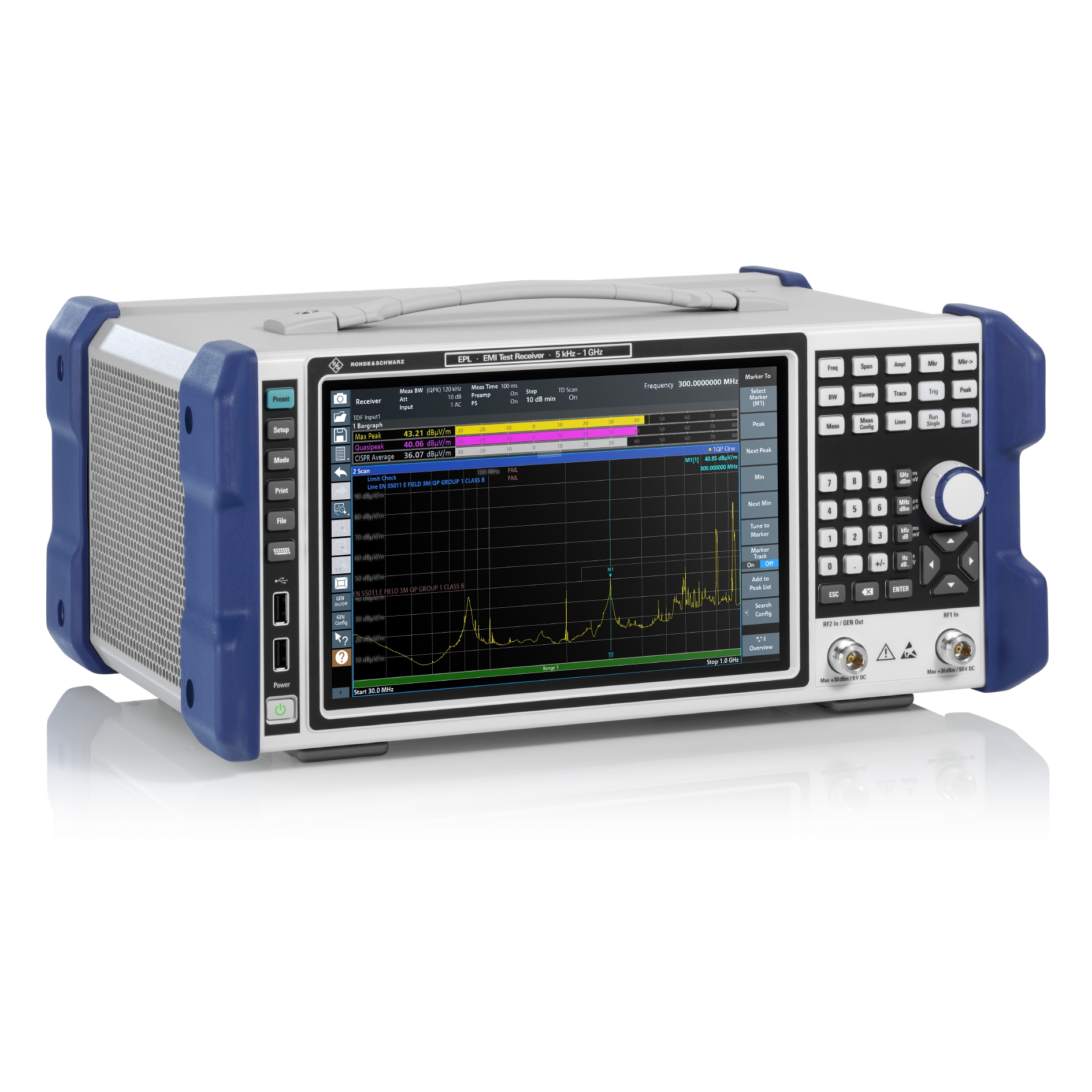
In the development lab, a spectrum analyzer is a common instrument of choice to quickly build an overall understanding of the emissions and interference sources, typically using a near-field probe. Typical checks include looking for obvious sources of noise including switching regulator noise or high-frequency PWM signals such as display and backlight drivers, harmonics of system clocks, noise coupled into ground planes or I/O lines, and unintentional antennas such as long PCB traces and cables. Less obvious problems include periodic spikes or broadband bursts, conducted emissions, and noise resulting from poor layout or split ground planes.
On the other hand, intermittent or sporadic interference triggered by specific conditions can be difficult to find and special features like advanced triggering or real-time analysis are needed to capture time-correlated events. Some EMI issues like ground loops or cross-system coupling only emerge when multiple subsystems interact and may not be visible when probing individual boards.
Overall, “sniffing around” the assembly with an old spectrum analyzer can be time consuming and may fail to discover certain types of problems. Sometimes, this approach needs a seasoned engineer’s experience to reveal elusive sources of unwanted noise.
Efficient Evaluation
A test receiver can detect and characterise diverse types of interference with ease. Equipped with CISPR-16 EMI detectors as standard and modern EMI debug features, it can detect time-varying or intermittent emissions that simple peak detection on an old spectrum analyzer would underestimate or miss entirely.
Typically used in formal radiated and conducted emissions testing, this type of instrument is well suited to capturing standardised measurements and can accurately assess emissions to provide precise, full-compliant results. The test receiver can offer even greater help to engineers when equipped with tools such as real-time spectrogram, time-domain analysis, and click analysis for assessing discontinuous disturbances from electromagnetic switches such as relays and contactors.
Although mandatory only for certain products as covered by CISPR 14, typically home appliances, click testing can give valuable insights for debugging other categories of equipment that may not be subject to compulsory testing. Automotive systems are an obvious example, where motor-driven mechanisms such as fans and pumps, heaters, lighting, and others are constantly activated and deactivated during normal operation of the vehicle. Identifying and minimising these emissions can improve coexistence between the many systems on board.
Clicks, which are short emissions and can be either sporadic or burst-like, are often difficult or impossible to detect using ordinary continuous scans. Analysis requires a test receiver that supports automated click counting and timing. This combines well with user-interface graphics that let developers zoom in on individual clicks, measure timing and amplitude, and correlate the clicks with specific operations in the equipment being tested. Automated analysis like this is faster and easier than checking raw EMI data, making debugging more efficient, and helps find intermittent signals that could otherwise be missed.
By performing standard-compliant click rate analysis at 150kHz, 500kHz, 1.4MHz, and 30MHz, R&S EPL test receivers can measure all four frequencies in parallel and capture measured values in real time, frequently updating the display showing number of clicks, click rate, and limit of continuous disturbances. The memory depth permits gapless measurement for up to four hours and can record peak values and quasi-peak values for two hours as required in CISPR 14. The software also generates a detailed test report automatically and a pass/fail statement that indicates whether the equipment as tested complies with the standard.
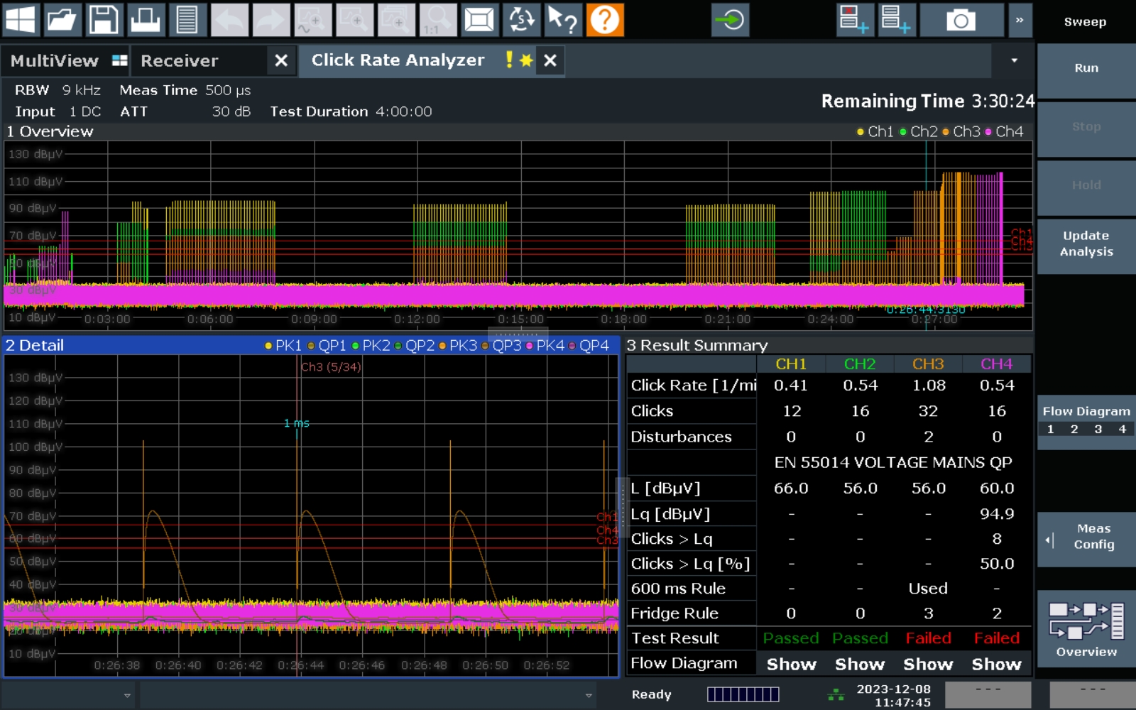
The detail window in the bottom left shows a limit is exceeded on the quasi-peak detector and is counted as a click. This complements the timeline at the top displaying the clicks over the full test time
Spectrogram and Time-Domain Analysis
Another known strength of test receivers is the ability to automatically capture measurements across a broad frequency spectrum and use these to produce a real-time spectrogram. This can help both localise a source of interference as well as characterise the behaviour to help analyse a noise source in detail.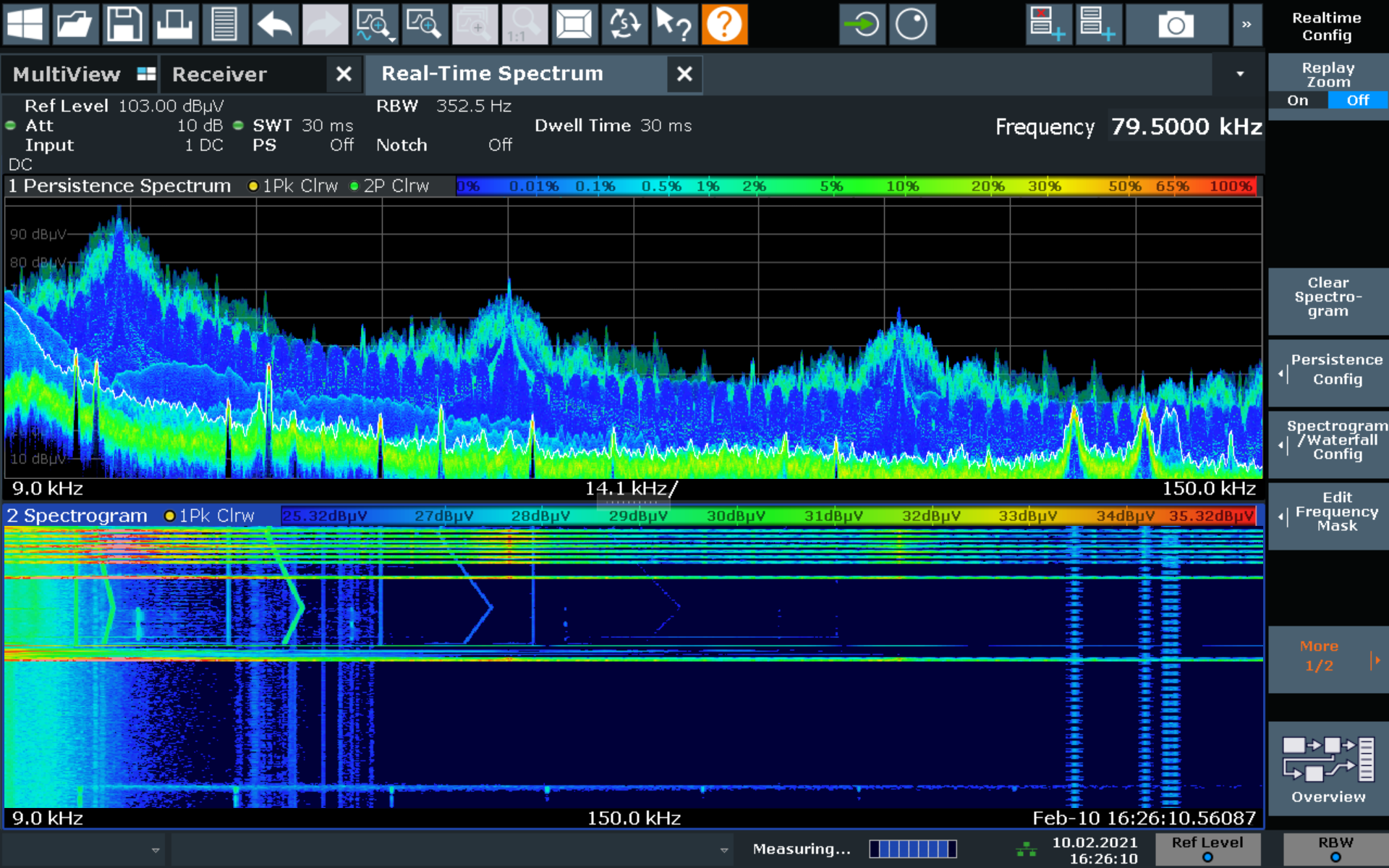
To perform a step scan, the test receiver compiles the spectrum from individual Resolution Bandwidth (RBW) measurements. Although this simplifies the task from the user’s standpoint, a complete scan can take hours to complete, depending on the frequency range selected and measurement time required to capture the product’s full duty-cycle.
By implementing a high-performing FFT algorithm, instruments like the R&S EPL test receivers can provide gapless measurements that detect every emission within a wide frequency range. Long measurement times are possible and any dependencies between the emissions are easy to see because all measurements belong to the same time segment. By selecting the appropriate settings and Fast Fourier Transform (FFT) parameters, the instrument can produce measurements across CISPR band A (9kHz-150kHz) or band B (150kHz to 30MHz) in one shot, measuring at the specified resolution bandwidth (RBW).
Frequency ranges above 30MHz are measured in multiple steps of 20MHz. In all these ranges, up to three traces can be activated at once with different detectors (including CISPR detectors). This enables fast standard-compliant EMI measurements directly with the detector required by the standard.
Testing from Concept Validation to Production Validation
The test receiver is conceptually intended for formal testing and hence has historically been seen as relatively expensive as an instrument for ad-hoc use in the development phase. The R&S EPL receivers address this through modularity that allows an entry-level configuration to provide the capabilities typically needed at the start of development.
While formal specifications typically mandate testing at frequencies up to 6GHz, and 7.125GHz in the case of some proprietary automotive schedules, most “problematic” interference signals typically exist at frequencies below 1GHz. The new R&S EPL models permit scaling the measurement frequency range to allow an affordable price for development purposes.
This means the most basic configuration of the EPL1001, having a limit of 1GHz, can be increased at a later stage up to 7.125GHz, to replicate the formal tests that will be performed at the test house. Similarly, the click-rate analysis module and other useful features can be added when needed to spread the cost of investment. The instrument is portable and easily moved between laboratories and dedicated test areas as needed.
Addressing EMC engineering challenges
Commonly deployed in formal test houses for ensuring compliance with electromagnetic compatibility (EMC) regulations, test receivers provide valuable capabilities for detecting and dealing with troublesome emissions during product development. The typical functions allow for in-depth EMI signal analysis, giving product developers crucial information needed for a successful validation program. A portable test receiver with flexible configurability, that lets users tailor the instrument to their specific needs and budget as their requirements evolve, can address EMC-engineering challenges across the development lifecycle, from Concept Validation (CV) to full compliance Production Validation (PV) testing.


