News

Anritsu Enhances Protocol Test Solution Supporting NTN NB-IoT Devices for GEO Satellites

Anritsu Corporation has extended the functionality of its Signalling Tester MD8430A with the introduction of a protocol test solution for Non-Terrestrial Network (NTN) devices for Geostationary Earth Orbit (GEO) satellites. As a result of the upgrade, the MD8430A can now support NTN Narrow Band Internet of Things (NB-IoT) technologies.

NTN NB-IoT is an IoT communication service for areas that terrestrial base stations cannot cover and is used in such fields as maritime shipping, logistics, mining, and automobiles. It enables a host of IoT devices to connect to the network with low power consumption. Its current specification is 3GPP Release 17. With this functionality enhancement, Anritsu will help to improve the quality of NTN devices and contribute to the realization of a prosperous network society.

Development Background

In the past, individual satellite operators have offered proprietary satellite communication services. However, since the standardization of NTN communications in 3GPP Release 17, the satellite communication service market has rapidly grown, and various verifications based on the standard specifications have become necessary. For GEO satellites, NTN device vendors need test environments that can simulate the communication delay over a distance of approximately 36,000 km between satellite and device. Satellites must also transmit information over this distance to the device for delay compensation. To support these test requirements, Anritsu has developed a protocol test solution that boasts high reliability built on test experiences with market-leading customers and high flexibility in condition setting.

Product Outline

The MD8430A is a base station simulator that can build a simulated network necessary for the development of chipsets and devices. With its software option NTN NB-IoT (GEO) MD8430A-043 and its control software option NTN over IoT Framework for RTD MX800050A-070, the MD8430A can be connected to an NTN device for GEO satellites, which makes it possible to test the connection with the NTN network and roaming between the terrestrial network and NTN network, among others.

The crucial role of I/O communication

GDevCON, a high-level technical event for LabVIEW architects, is not your typical conference. Held over two days in the iconic Glasgow Science Centre, it offers a unique space for collaboration and idea-sharing, free from corporate oversight or control. Here, Chris Knight, technical support engineer at automation and control technology specialist, Beckhoff UK, a gold sponsor at the event, explains the key take aways and the vital function that Inputs and Outputs (I/O) communication plays in connecting systems, exchanging data and ensuring efficient automation.

Unlike trade shows, GDevCON is all about bringing LabVIEW experts together to exchange knowledge and foster a developer community. But what truly sets the event apart is the emphasis on credibility, as exhibitors must know at least one attendee, who either develops or works in LabVIEW, to join.

With that in mind, it was impressive to see GDevCON 2023 welcome approximately 200 attendees, including representatives from organisations like SpaceX, CERN, nuclear research facilities and large National Instruments (NI) systems integrators. It also attracted participants from 23 countries, including the USA and India, along with the presence of five NI employees.

From the numerous talks and conversations that took place, we quickly realised that many of the manufacturers had gaps or deficiencies in their existing production lines.

More specifically, these companies claimed to be absent from — and in need of — cost-effective options for motion control, fieldbus communications and a more extensive I/O range.

Motion control

Motion control, also known as servo control or robotics, is a branch of automation that focuses on precisely controlling the movement of various components inside a machine. The movement of these different parts are usually controlled by rotary and linear actuators.

Machine position and velocity can be regulated using a motion control device, like an electric motor, hydraulic pump, or servo actuator. Typically, industrial operations use motion control to move specified loads carefully, hence controlling the movement of objects falls under motion control.

A challenge in motion control for manufacturers is the delicate balance between precision and efficiency. Achieving highly precise movements in industrial processes is vital for quality and consistency, yet this level of precision often comes at the cost of increased energy consumption and slower production speeds.

Highly precise movements demand meticulous control, which may require more time and energy. However, striking the right balance is essential as motion control systems enhance efficiency, quality and competitiveness in a variety of industries, from manufacturing and robotics to aerospace and healthcare.

Fieldbus communications

Efficiency and movement precision are critical in manufacturing lines. However, fieldbus communication is essential to unlock these benefits.

Firstly, fieldbus networks are a means of communicating with input devices and output devices, without having to connect each individual device back to, for example, the PLC or industrial PC.

Before its introduction, computers would connect using direct serial connections whereby only two devices could communicate per connection. Whereas the fieldbus allows hundreds of analogue and digital points to connect simultaneously, which not only reduces the number of cables required but also cuts down cable length too.

In an industrial setting, this ensures the integration of numerous devices, along with standardised communication and compatibility. Be it in a single machine or across a large plant, the fieldbus network is a significant component that lays the foundations for scalability and dependable industrial automation options.

All about the I/O

By serving as the communication backbone, fieldbus allows various I/O devices to share information efficiently. Here, sensors collect data and send it to the fieldbus, while actuators receive commands from the same network.

This integration streamlines control, reduces wiring complexity and centralises monitoring, making it ideal for applications with extensive I/O requirements. However, those without an extensive I/O range can come across problems, especially in terms of scalability.

For instance, a narrow I/O range may create obstacles for manufacturers wanting to meet the diverse needs of their customers, because they lack the necessary sensor and actuator options. This, in turn, restricts market reach due to the limitations in being able to alter production lines for custom products.

This reinforces the critical role I/O plays, as without it, industrial and electronic devices would not receive data. In essence, it forms the bedrock of industrial control and data processing, with I/O modules serving as intermediaries between a central processor and the industrial device to ensure connectivity.

For instance, within a programmable logic controller (PLC), input modules can receive signals from switches, sensors, transmitters, actuators and other connected equipment. While output modules on the PLC transmit response signals to the devices controlled by the PLC in response to the received signals.

EtherCAT is the answer

EtherCAT is a communication protocol often used in industrial automation where quick data exchange between devices is essential, including those within a PLC. Moreover, it is highly scalable and can accommodate a large number of devices on a single network, making it suitable for both small-scale and large-scale industrial applications.

Digital options, such as Beckhoff’s TwinCAT automation software, offers EtherCAT as a primary communication option. This not only enables users to configure, manage and control EtherCAT-based automation systems, but also provides EtherCAT Master functionality too.

For example, PLCs connected via EtherCAT can connect and control various aspects of the assembly process, ensuring synchronised movement of robots, conveyor belts and quality control sensors for precise coordination.

It must also be noted that this prevents companies from having to design raw data to scaled values in-house. Instead, the software has the modules to do that for you — a need that was highlighted at GDevCON and one that helps to plug the gaps in a plant’s production line.

If you’d like to learn more about Beckhoff’s secure communication protocol, TwinCAT and other control technology, visit www.beckhoff.com

Understanding the thermal loop

Heat treatment processes are a crucial component of many manufacturing processes, but precise control of temperature requires more than just heating control. This is where the thermal loop comes into play. Thermal loop solutions have become increasingly popular for achieving improved temperature control and consistent outcomes, but what exactly does the thermal loop mean? In this article, Andy Selvy, chief system designer at industrial technology company Watlow, offers his insight.

A thermal loop is a system designed to precisely control the temperature of an object, fluid or gas. It comprises a closed loop system with vital components, such as an electrical power supply, power controller, heating element, temperature sensor and process controller. The electrical power supply furnishes the necessary energy for heating, while the power controller modulates the power output to the heating element. Subsequently, the heating element raises the material’s temperature, and the temperature sensor gauges the temperature. Ultimately, the process controller fine-tunes the power output to sustain the desired temperature for the specified duration, ensuring improved temperature control and consistent results. In some cases, a single component can play multiple roles.

For example, with high temperature coefficient of resistance (TCR) materials, it’s possible for a single component to act as both a heater and a sensor, which cuts down on the total number of components and wires needed in the system. Altogether, these parts create a system known as a thermal loop that can maintain process temperatures automatically through time.

How does it work?

A home thermostat is a simple, everyday example of closed loop temperature control. You can adjust the temperature of the range, but this must be done manually. The system does not detect temperature or adjust itself — it only provides heat. A homeowner could set a thermostat and leave it for months, never having to actively direct or control the system, but the system would maintain the same temperature range during that time. They work well for heating our homes, but certainly come with limitations with regards to temperature control.

The limitations seen with traditional thermostats provide a good parallel for understanding the challenges that industries face when it comes to process heating and thermal control. For instance, heaters are typically controlled by consistently monitoring the power being provided. If power can be controlled in a more precise manner, then heaters can be better controlled and heater life can be extended. This often requires going beyond simple “power on or off” switches and introducing advanced forms of power control.

Temperature sensing needs to be done in multiple zones, not just one place. For example, a surface for creating semiconductor chips might need to be divided into several zones so that temperature uniformity can be achieved at each point — much like having a thermostat in every room of your house.

Systems thinking versus component thinking

This is why systems thinking is so important. Even if you find that “best” component — the best heating element, the best sensor, the best power controller — it does not mean that you have found the best component for that particular application and system. Problems often arise not necessarily because of an issue with the right component, but rather the way the entire system has been engineered.

This can include temperature sensors that are either too close or not close enough to the heating elements, which create an unreliable picture of the temperature on a heater surface or within a heated space. Small fluctuations in temperature at the heating surface can lead to “hot spots” which, over time, can cause scorched material accumulations that can foul up the equipment, resulting in equipment failure. Lastly, the power needs and input to the system fluctuate over time, leading to inconsistent heating even when sensors are recording the correct temperature.

Thermal loop applications

There are many applications where the control of thermal processes matters. This includes semiconductor processing, energy generation, materials processing, medical devices and food and beverage equipment.

Within each of these industries are sensitive processes that require varying levels of temperature regulation. For example, when a manufacturing process molds and shaping metal, the equipment needs to maintain a temperature above a certain threshold. But an exact temperature may not be necessary. So, why do we talk in terms of “thermal loops” at all? Why not just talk about heaters, sensors and power controllers themselves? Granted, naming the parts of the thermal loop and understanding their features is easier. But these individual components are just that — components.

Understanding the thinking that goes into choosing the right components, and putting them together, is a far greater challenge. This is where Watlow’s thermal expertise comes in. For Watlow, the underlying concept behind its entire offering is of the thermal loop. Currently, some of the applications where Watlow is solving complex thermal problems include respiratory devices, analytical equipment, oil and gas processing and semiconductor processing.

The thermal loop is an idea that not only gives structure to what Watlow offers, but also contributes to the structure of a thermal system as a whole. Understanding the thermal loop for a given application requires an appropriate understanding of the components in the loop. But more than that, it requires bigger picture thinking that considers how the various components need to work together and how they will be embedded in an application to achieve various goals.

To discover more about Watlow’s thermal solutions, visit the website.

Teledyne FLIR at Middle East Energy 2024

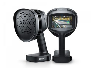
Cutting energy costs, reducing loss, and downtime, Teledyne FLIR, is all set to showcase their Electric Utility Solutions product portfolio at Middle East Energy 2024 scheduled from 16th to 18th April at Dubai World Trade Centre.

Exhibiting at Stand H4 E30, Teledyne FLIR will showcase energy-saving solutions such as Industrial Acoustic Imaging Camera, Handheld Thermal Cameras, Fixed Thermal Cameras, and Test & Measurement equipment.

The ground-breaking product on display is the FLIR Si2-Pro™, an industrial acoustic imaging camera for partial discharge detection, pressurized leak detection and mechanical fault detection. The FLIR Si2-Pro helps you significantly lower costs associated with mechanical bearing issues and partial discharge on electrical equipment. It also enables you to drastically reduce leaks in your facilities, cutting down expenses related to compressed air and gas leaks. With the Si2 series, you’ll experience the best-in-class performance, decision support, fleet management, and enterprise data integration available.

In addition to the FLIR Si2-Pro™, Teledyne FLIR will also showcase the following solutions:

FLIR Exx-Series

The FLIR E76, E86 and E96 offers a range of full-featured handheld thermal cameras fit for every budget, making all your inspections more convenient. To make your processes even more efficient, you can also pair your camera with a FLIR FlexView™ dual field-of-view lens to easily switch from wide-area to telephoto scanning, providing you with a comprehensive solution that involves much less hassle, effort, and time.

FLIR T-Series

Whether it’s your responsibility to maintain a factory’s uptime or keep the power flowing through distribution networks, FLIR T-Series thermal cameras offer the flexibility, precision, and features needed to inspect equipment safely and prevent breakdowns. From the 180° optical block rotation on T500-Series models, to the OSX™ Precision HDIR optical system designed exclusively for the T1K, the T-Series offers the next level in design and performance.

FLIR G306 Optical Gas Imaging (OGI)

The FLIR G306, a portable, non-contact innovative Optical Gas Imaging (OGI) camera is used to safely and efficiently scan sulphur hexafluoride (SF₆), ammonia (NH), ethylene (C₂H₄), and other industrial harmful gas leaks in various environments without interfering with electric utility delivery or shutting down industrial operations.

FLIR and EXTECH Test & Measurement Equipment

Intelligent and tough, FLIR and EXTECH Test & Measurement instruments are designed to meet the challenges of your industrial application.

For more details on innovations and offerings visit Teledyne FLIR stand H4.E30
Date: 16th- 18th April, 2024.
Location: Dubai World Trade Centre.

Custom ICs for enhanced high-precision metrology

Manufacturers who need high positional accuracy for their machinery rely on the accuracy of metrology technology. Here, Ross Turnbull, Director of Business Development and Product Engineering at ASIC design and supply company Swindon Silicon Systems, explains how custom Application Specific ICs (ASICs) offer enhanced precision for even the most demanding measurement applications.

Metrology instruments are a crucial element of the manufacturing plant. Whether for calibrating production machinery or for post-production verification, metrology equipment goes a long way in ensuring a high-quality finished product that meets specification.

Coordinate measuring machines (CMMs) are an example of a metrology instrument, able to provide measurements in all three dimensions. In post-production quality processes, CMMs are used to measure the geometry of physical objects for any manufacturing flaws or errors. This is achieved with a scanning probe by measuring discrete points or lines across the object. Control of the probe angle is also possible, allowing the machinery to measure surfaces that would be otherwise unreachable.

Converting the motion of the scanning probe into useful positional information is possible with the use of encoders. Encoders combine a scale, similar to the markings on a conventional ruler, with a readhead describing motion relative to the values on the scale.

Exploring CMM circuitry

The encoder typically converts a physical stimulus into an analogue signal. For this signal to be understood and interpreted by digital devices, including the metrology software, this signal must first be digitised.

It’s possible to use a variety of off-the-shelf integrated circuits (ICs) to perform the necessary tasks of signal amplification and conversion. However, for an optimised solution, the roles of these individual ICs can be condensed into a single chip: an ASIC.

An ASIC is a chip that has been designed exactly for customer requirements. A complete custom design approach results in a high-performance IC with capabilities beyond those offered by standard off-the-shelf devices.

By taking a careful approach to design, it’s possible for an ASIC to encompass all the features of several standard ICs in one package. Consolidating functionality into a single package typically allows for a reduction in PCB size. A more compact size allows for a smaller and lighter encoder that can be easily designed into CMM equipment.

ASIC design also facilitates greater performance where it matters. In a position sensor, this might be a non-linearity specification for improved sensor calibration and accuracy. This is where working with an experienced ASIC designer can be hugely advantageous; the entire signal path can be optimised for a chip that offers both the technical and commercial advantage to the customer.

In metrology, even a minute fraction of a millimetre could be the difference between product success and failure. As a result, it’s vital that metrology equipment and the sensors within are class-leading. With the help of ASICs, accuracy of these devices can be enhanced for improved product quality and efficiency.

The good, the bad and the future of generative AI

Douglas Eck, principal scientist at Google Research said, “Generative AI is like having a thousand artists at your fingertips, each with their own unique style and perspective.” This also translates into the manufacturing industry, where generative AI is being introduced at every step, from design to maintenance of assets. Here Stephen Hayes, managing director of automation and control technology specialist, Beckhoff UK, explores the benefits and risks of introducing generative AI into your manufacturing process.

According to a report by MarketsandMarkets, the global market for generative AI in manufacturing is expected to grow from $73 million in 2020 to $181 million by 2026, at a CAGR of 16.4 per cent during the forecast period. The report also notes that generative AI is being used in various manufacturing applications, including design optimisation, process optimisation and predictive maintenance, among others.

Benefits to manufacturing businesses

The benefits of using generative AI in manufacturing are clear in a recent case study from Siemens, who used generative design to optimise the design of a gas turbine blade. The AI generated thousands of potential designs, which were then evaluated for their performance and manufacturability. The final design was not only more efficient, but also reduced the number of individual components needed to make the blade, resulting in cost savings and a shorter manufacturing time.

As well as optimising designs, generative AI can be used in engineering and manufacturing to reduce material waste and improve production processes. It can help generate new ideas for designs based on specific criteria and constraints, simulate and test different scenarios, and provide insights to improve efficiency and quality. It can also aid in predictive maintenance and quality control.

With a significant skills shortage in UK manufacturing, particularly in areas such as engineering, robotics and automation, the introduction of generative AI could help bridge this gap. Not only can it help automate and optimise processes, but it can also free up skilled workers to focus on more complex tasks.

Additionally, generative AI can assist in training new workers by providing virtual simulations and personalised feedback to accelerate their learning. This could be vital in the coming years, since Make UK recently reported that there are around 84,000 live vacancies in UK manufacturing, slightly down from 95,000 in 2021, which represented the highest in at least 20 years, but still massively above the desired number.

Introducing challenges

Despite its clear benefits, the use of generative AI also poses significant cyber security risks. A recent report by Deloitte stated that the manufacturing industry has experienced a 300 per cent increase in cyberattacks since 2018. Additionally, a survey by the National Association of Manufacturers found that 38 per cent of manufacturers had experienced a cyber-attack in the past twelve months.

While these can’t wholly be attributed to the growth of generative AI, it certainly has a part to play, with programmes like ChatGPT being used to create worryingly convincing phishing emails. Manufacturers should ensure staff are suitably trained to recognise this latest evolution in phishing messages to avoid falling victim to an attack.

One of the main risks associated with generative AI is the potential for hackers to manipulate the algorithms used in the design process. This could result in the creation of flawed or malicious designs that could cause serious damage to equipment or even harm individuals. Additionally, hackers could use generative AI to create counterfeit designs, leading to intellectual property theft and revenue loss for manufacturers.

Another significant risk is the potential for data breaches. Generative AI relies heavily on data input, and if this data is compromised, it could be used to create faulty designs or even shut down production processes. This could result in significant financial losses for manufacturers and pose a threat to national security in industries such as defence.

However, cyber security isn’t the only challenge that generative AI introduces. Generative AI can sometimes produce designs that are difficult to interpret, making it challenging to identify potential flaws or vulnerabilities. To mitigate this, manufacturers should ensure that their AI systems are transparent and explainable to enable effective risk assessment.

To overcome these challenges, manufacturers and engineers must prioritise cyber security and data management. This involves implementing robust security protocols, such as encryption and multi-factor authentication, to protect sensitive data. Regular risk assessments and penetration testing should also be conducted to identify vulnerabilities in systems.

Cyber security is also becoming even more of a priority at machine-builder level, where industrial equipment is being designed with secure communication protocols, such as TwinCAT, in mind. This involves using encryption techniques to protect data transmission between equipment and other systems, as well as implementing secure authentication processes to prevent unauthorised access.

With an aging workforce and a lack of younger people entering the industry, it’s clear that the UK’s manufacturing sector will face an ongoing shortage of workers. Embracing technologies like generative AI could go some way in overcoming it, but it’s important that the correct measures are taken to ensure that the technology doesn’t leave manufacturers open to catastrophic security breaches.

For more information about Beckhoff’s secure communication protocol, TwinCAT, and other control technology, visit www.beckhoff.com

Selecting the right IC for your application

When it comes to hardware design, system engineers have more than one architecture to choose from. Both Application Specific Integrated Circuits (ASICs) and Field Programmable Gate Arrays (FPGAs) can offer benefits, but which one is best for your application? Here, Ross Turnbull, Director of Business Development and Product Engineering at ASIC design and supply company Swindon Silicon Systems, explains what to consider.

To start understanding the differences between an ASIC and an FPGA, we begin by defining the two. An ASIC is a type of IC that has been designed uniquely for its target application, whereas an FPGA is typically a standard part that is user-configurable and can fulfil multiple purposes. FPGAs can be reprogrammed one or more times to perform a variety of tasks.

At first glance, the distinction between the two seems simple: one has been carefully optimised, the other built for flexibility. But when it comes to choosing between an ASIC and an FPGA for your specific application, the differences can be a lot more nuanced. So, what factors should you consider?

How fast do you need to get to market?

If time-to-market is of the utmost priority, an FPGA will likely be the preferred route. Unlike ASICs, which involve a rigorous custom design process, FPGAs are typically sourced off-the-shelf. Equipped with a standard interface, FPGAs can be easily reprogrammed by the customer for specific functions, enabling quick and easy product integration. This makes them ideal for dynamic fields where the environment and expectations are changing quickly, and these factors are prioritised over cost considerations.

But if you’d like the optimised performance of an ASIC without an extensive timeframe, there are routes available to make this possible. ASIC designers have access to one or more libraries of foundry and third-party IP. These IP blocks can be used to form the basis of a custom IC design, shortening development time without losing the optimisation benefits of an ASIC. Software can also be developed in parallel to the hardware, further shortening the project timeline.

Digital, analogue or both?

FPGAs are best suited to realise digital circuitry. While it’s possible to include analogue blocks onto the FPGA silicon to provide both digital and analogue compatibility, these blocks often don’t have the desired performance.

In this scenario, the ASIC provides a distinct advantage. A variety of analogue components including analogue to digital converters (ADCs), amplifiers, voltage regulators, filters and synthesizers can be combined with digital devices in a mixed-signal ASIC solution. Advanced communication protocols such as Bluetooth Low Energy (BLE) can also be incorporated into the design.

Cost and volume

The cost factor depends largely on the scale of production required. ASIC design and development stages mean that they typically have a higher non-recurring engineering cost (NRE) than FPGAs. However, ASICs will often have a lower cost per unit. This is due to the removal of unneeded functionalities, reducing overall silicon size and bill of materials. As a result, while the initial cost and time investment for ASIC design is higher, it typically offers a much better ROI on for larger or longer production volumes.

Performance

While a reprogrammable FPGA will be able to perform a wider variety of tasks, an ASIC will always offer the superior performance for the exact task it’s been designed for.

This tailored approach means that the ASIC can offer significant technical advantages over FPGAs and other solutions on the market. For instance, wearable applications requiring a compact chip with an extended battery life will likely benefit from the ultra-low power circuitry that can be best achieved with an ASIC.

To illustrate this, it’s possible to look at Swindon’s own development. ASICs in our tyre pressure monitoring system (TPMS) family must have a minimum operational lifespan of ten years, powering a MEMS pressure sensor, microprocessor and RF transmitter — all from a single coin cell battery.

Decline and obsolescence

FPGA supply, like many other off-the-shelf solutions, is determined by the manufacturer. If supply drops below a minimum level, the manufacturer may halt production of new FPGA chips and issue a notification of obsolescence. Following this, it’s down to the customer to identify an alternative. This could be the purchase of leftover chips or sourcing a similar product from a different supplier. Either way, obsolescence is often a tricky area to navigate and a headache for purchasing and procurement professionals.

An ASIC is slightly different. Rather than the manufacturer deciding to halt production, the equivalent in ASIC terms would be the silicon process going obsolete. When designing a custom IC, the supplier will take care to ensure the silicon process chosen meets the expected lifetime of the product. But in the unlikely event obsolescence occurs earlier than expected, a reputable ASIC company will work with the customer to find an alternative solution.

It’s possible to port the design onto a newer silicon process instead. Wafers can also be purchased and stored for several decades in dry nitrogen cupboards. Depending on the needs of the customer, these steps can be taken alongside the commencement of a new ASIC project. The benefit of this rounded approach is it means the customer will always have sufficient product to fulfil orders between the old and new ASIC.

At first, the differences between an ASIC and FPGA can seem quite straightforward. But when it comes to identifying how each one might benefit your specific application, it requires a much more thought-out approach. Considering cost, time-to-market, obsolescence, and other key factors is essential to ensure you have a chip that meets all your product’s needs, both for the current and future iterations. 

To discuss your project and find out if an ASIC solution is for you, visit our website to book a consultation with a member of the Swindon team today.

element14 Community and Infineon host educational webinar series on ModusToolbox software

element14, an Avnet Community, is working with Infineon to host the four-part webinar series, “ModusToolbox™︎ Workshops: From Getting Started to Custom Hardware,” to showcase ModusToolbox™︎ software, a popular Infineon offering used for efficient embedded development.

These webinars, led by Clark Jarvis, Software Technical Marketer at Infineon, will provide an understanding of ModusToolbox™︎ and related embedded development concepts. Each webinar will build in complexity, starting with the basics of using the software and ending with the steps to port the application onto custom hardware.

“I know our Community members will appreciate the opportunity to build upon their knowledge and implementation of the ModusToolbox™︎ software with each webinar,” said Andreea Teodorescu, Global Director of Product Marketing & element14 Community. “Though the webinars can be watched as stand-alone videos, they will increase in complexity to provide a holistic overview for our members of this software.”

The first webinar in the series, ModusToolbox™︎ Workshop 1: Understanding the Conceptson Wednesday, 20 March at 5 p.m. GMT / 12 p.m. ET will share:

  • An introduction to ModusToolbox™︎
  • Workflow options for supported IDEs
  • How to integrate and manage middleware
  • Overviews of API functions available for PSoC microcontrollers

The second webinar in the series, ModusToolbox™︎ Workshop 2: Getting Started Using CAPSENSE™︎ Capacitive Touchon Wednesday, 3 April at 5 p.m. GMT / 12 p.m. ET will explore:

  • Creation of a ModusToolbox™︎ application
  • Integration of CAPSENSE middleware
  • Leveraging the CAPSENSE Tuner application to visualize touch performance

The third webinar in the series, “ModusToolbox™︎ Workshop 3: Connecting using Wi-Fi and MQTT on Wednesday, 17 April at 5 p.m. GMT / 12 p.m. ET will delve into:

  • Available ModusToolbox™︎ connectivity examples projects
  • Connecting the development board to Wi-Fi
  • Leveraging a local MQTT broker to publish and subscribe to messages
  • Connecting the application to AWS

The fourth and final webinar of the series, ModusToolbox™︎ Workshop 4: Porting an Application to Custom Hardwareon Thursday, 2 May 2 at 5 p.m. GMT / 12 p.m. ET will highlight:

  • The concept of a ModusToolbox™︎ BSP
  • Creation of a custom BSP based on a hardware schematic
  • Moving the existing application to the custom hardware

The series will leverage the CY8CPROTO-062-4343W development kit featuring the PSoCTm 62 microcontroller.  Participants desiring to follow along can order the board, however, having a kit is not required to benefit from this workshop.

Participants can test their knowledge on a short quiz and earn a certificate upon completion. The quiz will also be available for those who watch the webinar recordings available On Demand.

To learn more and register for the webinar series, please visit element14 Community.

Sensing unwanted bubbles brings awards recognition

The nomination of the BAUMER PAD20 ‘Bubble Sensor’ for the 2024 Pump Industry Awards once again recognises the contributions and abilities of sensor specialists Baumer to push the limits of sensor technology. The innovative PAD20 sensor has been shortlisted for the international awards in two categories; ‘Product of the Year’ and ‘Environmental contribution of the Year’.

The PAD20 has been developed as a ‘smart’ sensor which helps to protect pumps from running dry whilst also helping to ensure maximum system performance and optimum use of resources. A key feature of the sensor is its ability to detect even the tiniest gas bubbles in liquids which helps system engineers in preventing downtime due to pump malfunction caused by unwanted gas inclusions.

However, the PAD20 sensor is not only good at protecting pumps as reliable detection of gas bubbles also optimises the energy efficiency of cooling and heating systems in industrial applications. The sensor has the ability to measure air in all types of liquids regardless of whether liquids are pasty or viscous, reliably and fast. Another good example is where the sensor has helped a major dairy manufacturer solve the decades old problem of containers not being fully emptied.

In summary, PAD20 sensors are an effective, robust solution for detecting air and gas bubbles in any liquid or viscous media such as fruit preparations, cooling agents (DC>1.5) and particularly in harsh ambient conditions. Switching outputs are individually adjustable with IO-Link (2) for definition of switching range, or two-stage alarms (early warning) and they provide optional multi-colour process visualisation through 360º of switching state.

More at: https://www.baumer.com/de/en/pump-industry-award-2024-baumer-bubble-sensor-pad20-named-finalist/n/news-industry-award-nomination

Pulsiv & Astute Electronics join forces to co-exhibit at PCIM Europe 2024

Pulsiv Limited, the Cambridge (UK) innovator of power electronics technology, is joining forces with global electronics distributor & supply-chain expert, Astute Group to co-exhibit at Europe’s foremost power electronics exhibition & conference, PCIM Europe. Following the recent expansion of their distribution agreement, this collaboration demonstrates a firm and strategic commitment by both companies at what is arguably the most important European event for the power electronics sector.

Nick Theodoris, Director of Global Sales & Distribution at Pulsiv comments: “I’m delighted that Pulsiv and Astute will collaborate at PCIM Europe 2024. It enables us to have a more prominent presence at such a key industry event, while showcasing our ground-breaking power electronics technology alongside a respected name in franchised distribution. As we launch our world-leading USB-C reference designs and finished modules, we recognise the value partners bring in helping us gain maximum market exposure and drive sales globally. We continue to expand our strategic alignment with Astute and look forward to what promises to be a very exciting and lucrative event.”

Mark Shanley, Sales & Marketing Director at Astute Group said: “Astute is a growing force in European electronics distribution, so we’re excited about this opportunity to showcase our expanded partnership with Pulsiv at PCIM Europe 2024. This collaboration underscores the strength of our commitment to bringing innovative, energy saving power electronics to the European market. We’re anticipating a highly successful show.”