Advertorials

The Problem

A customer came to us with a requirement to measure the torque setting of air drivers being used on an assembly line. They had been experiencing fasteners being damaged and suspected that incorrect torque settings were causing the issue.  Testing had to be carried out on the assembly line, which had multiple workstations. A portable, yet robust and accurate test solution was required.

The Solution

We were able to help with the USB version of our T15, Hex Drive rotary torque transducer.

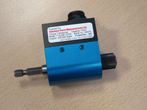
The T15 is a contactless design torque transducer, capable of up to 2,500 samples per second at 4,000RPM to an enhanced accuracy class of 0.1% full scale. The USB version offers the additional advantages of being powered by the USB connection to a PC or laptop, so no external power is required.

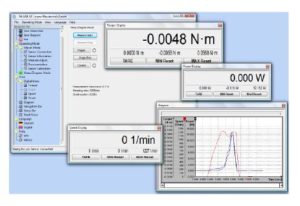
In addition, the T15-USB is supplied with our BluDAQ, Windows compatible data logging software, enabling view live data viewing and automatic data logging. Data can also be exported in BMP or CSV file formats for further analysis in other software packages.

The T15 torque transducer could be installed quickly and easily between the air driver and fittings on each workstation.  This enabled data to be collected, viewed and saved in just a few moments. Any adjustments to incorrectly setup air drivers could be made and checked without a lengthy shutdown of the production line.  Saving time and money

The Range  

Interface Force Measurements offers a range of torque transducers with USB output. All with the same advantages of the T15.

The complete range consists of T12 – Square Drive; T15 – Hex Drive and T25 – Shaft style. All in capacities from 0.1 to 5,000Nm and capable of measuring at speeds up to 30,000RPM.

All these sensors are also available with analog, ±5vdc outputs.

BluDAQ Software

All our USB Torque Transducers are supplied with BluDAQ software from Interface Force Measurements, free of charge. BluDAQ is a fully-featured, Windows compatible data logging software package with

  • Torque, speed, and power OR torque = angle
  • Display, graph, and logging
  • Up to 2,500 measurements per second
  • 16-bit resolution
  • Peak & valley
  • Unit conversion
  • Triggered start & stop for automatic event capture
  • Automatic scaling of Y-Axis
  • Log files are in Excel-compatible .csv format
  • Power supply over USB – no separate power cord
  • Configuration & calibration stored in the sensor

All these features make the interface USB range of torque transducers offer a simple and convenient method of accurately measuring torque without requiring external power or excitation. Data can be viewed live and recorded. Triggered start and stop for automatic data capture ensures no data is lost.

If you would like more information about our USB torque transducers or any other of our force, torque or pressure measurement sensors, please visit our website,  interfaceforce.co.uk or contact us by calling 01344 776666 or by email at info@interface.uk.com

Achieving very precise measurement

There are many different types of current measurement technologies, from basic shunt and Hall Effect devices to more complex systems. The determining factor is usually the accuracy required, with emerging eV, solar, traction and power grid applications demanding accuracy levels to 100s of ppm, while medical MRI equipment and physics institute accelerators can require single figure ppm performance. At these higher levels, simple devices cannot deliver. Now, an eight year old Danish company, Danisense, is offering DC and AC current sense transducers based on its Fluxgate technology which provides measurements down to 1ppm.

Danisense proprietary fluxgate is a closed loop compensated technology with fixed excitation frequency and second harmonic zero flux detection. The magnetic field in the toroid generated by the primary current is counteracted by the compensating secondary current generated by the integrator. The Fluxgate detects magnetic fields in the toroid from DC to less than 100 Hz at sub ppm levels and tells the integrator to compensate for them. At higher frequencies, the feedback winding detects magnetics fields in the toroid at ppm levels and again tells the integrator to compensate for them. Figure 1 compares how the current behaves normally (red line) and then through the Fluxgate element (blue line). Through a pick up coil wound on standard magnetic materials, the current is linear until saturation. However, if magnetic materials for the core are chosen for their deep saturation and sensitivity, the graph changes to show a very definite and identifiable step change.

Figure 2 is a simplified plot showing the effect of applying a square voltage (left) resulting in sharp positive and negative signals, then if a primary DC current Ip through a wire conductor is introduced, a DC magnetic field is added which shifts the signal (right). Finally, an advanced signal processing is applied and by using second harmonics the values for the new signals can be extracted to provide a measurement of the current in the conductors and its DC current value. This is the basic FluxGate (or zero-flux) technology.

(This can be supplemented with an additional AC feedback winding to extend the frequency range of AC current measurements.)

A simple, single Fluxgate structure and magnetic core will provide accurate DC and low frequency AC measurements but has very low bandwidth so is not suitable for full-bandwidth AC measurement. Furthermore, effects of temperature and other environmental conditions mean that the magnetic field can drift. Some manufacturers use electronic compensation circuitry, which adds cost and complexity, and can also be prone to inaccuracy. By contrast, Danisense employs a dual balanced Fluxgate structure which employs two magnetic cores in opposition, similar in concept to a Wheatstone Bridge. This provides natural compensation, eliminating the effect of any drift. The block diagram is shown in Figure 3a and the simplified signal plot in Figure 3b. However, in order for the two Fluxgate elements to balance each other, they must be perfectly matched.

Danisense’s major product line is the DS series units, and products span 200-10,000A (DS200 – DR10000). Units feature excellent linearity (0 to FS) and have an offset stability with time of less than 0.1ppm/month and a flat bandwidth (DC to ~ several hundred kHz). Phase shift for AC measurement is industry leading – see Figure 4 – and both current output and voltage output models are available. Aluminium housings provide immunity to electro-magnetic and common mode noise (dv/dt).

New PCB-mount versions

Most recently, Danisense has launched its ultra-stable, high-precision DP series of PCB-mount current transducers for isolated DC and AC current measurement up to 72A. With a footprint of 64.9 x 60mm, a height of 32mm and light weight of 250g, this compact device is suitable for 1U power supplies and other space-constrained applications.

Benefitting from Danisense’s balanced closed-loop, compensated Fluxgate technology which provides a fixed excitation frequency and second harmonic zero flux detection for best in class accuracy and stability, DP series PCB-mount current transducers feature a maximum linearity error of 10 ppm and a measurement resistance of up to 100Ω at full scale.   Devices are programmable for 12,5A, 25A, or 50A usage via the PCB layout.

Applications include MPS for particle accelerators, stable power supplies, precision drives, battery-testing and evaluation systems, power measurement and power analysis.

Summary

By combining complex magnetic performance with advanced electronics Danisense provides efficient and precise solutions that match the requirements of worldwide customers in demanding industries. Perhaps the most demanding application for any current sense transducer is within the power supply for particle accelerators, so the company is especially proud that it has an active program with CERN.

7.0” Embedded TFT LCM with Android OS

Craft Data are always seeking new partners with exciting products to add to their impressive product portfolio, the latest addition is a brilliant range of embedded Android (Linux Ubunto option) TFT Display modules from their partner MarvSmart Technology Company. These embedded display systems are suitable for a host of human machine interface (HMI) applications within the medical, industrial and auto/aero markets.

Currently the most popular seller is the “MST10600L070”, a 7.0″ 1024×600 resolution IPS TFT LCM, incorporating a 10-point projected capacitive touch panel.  The standard version has a  brightness of 250cd/m² with (a high brightness model coming soon) ultrawide viewing angles of 80/80/80/80, and a “Free View” viewing direction, meaning the panel has no factory pre-set viewing direction allowing the module to be mounted in both landscape and portrait orientations without the loss of colour or image quality.

The embedded display system is powered by the high performance Rockchip RK3128 Quad-core ARM Cortex-A7MP, 1.2Ghz processor with an Android 7.1 operating system. Separate NEON (SIMD) & FPU co-processors enable accelerated signal and media processing plus an embedded Mali400 MP2 graphics processor unit supports smooth high resolution (1080p), high speed video content and graphics. 3 RS232 ports, 2 USB host ports plus WIFI and LAN (2G/4G & Bluetooth options also available) connections allow easy network communication and connection to your peripherals, a 2-Watt audio output, both left and right channels is also included. The standard configuration includes 1GB DDR3 plus 8GB eMMC memory for your application software however storage can be expanded further via a TransFlash card.

The compact module has an overall size of just 190.5 x 105.4 x 20.8mm and has an active area of 154.2 x 85.9mm, a flexible input voltage of between 7VDC and 24VDC and an operating temperature range of -20°C to 70°C makes the module suitable for a host of industrial applications.

Whilst the 7.0” size has to date been the most popular other sizes available within the range are an 8.0” 1024×768 resolution, 10.1” (1024×600), 15.0” (1024×768) and an 18.5” (1366×600) with other sizes under development.

Contact Info:

Craft Data Limited

Tel: 01296 332000

Email: sales@craftdata.co.uk

Homepage: www.craftdata.co.uk

Yokogawa’s TDLS analyser helps maintain safety, maximise efficiency and reduce costs

How safe is your asset?

The uncontrolled ignition of flammable components such as methane (CH4), carbon monoxide (CO), and hydrogen (H2) in the presence of combustion supporting oxygen (O2) can make chemical processing a hazardous activity, particularly in combustion.

It is essential to minimise hazards while complying with emission regulations, including ensuring there are no leakages in the heat exchanger or pipelines.

Chemical processing is based around three main objectives: maximising production, minimising cost, and ensuring safety is not compromised. The limitations of conventional technologies impact the capabilities of operators, maintenance and instrument engineers to meet these challenges.

A safe solution

Rather than saving money, hazardous operations and working processes cost much more due to production inconsistencies and downtime, and because of their limitations, conventional technologies have prevented operators from running processes in the safest manner.

Yokogawa’s Tunable Diode Laser Spectrometer (TDLS) analyser is a step change in operating safely, allowing O2 control while maximising efficiencies and minimising costs. It provides reliable, real-time, non-contact O2 measurement with minimum downtime, assured improvements in safety and negligible delay time to detect.

Data you can trust – in real time

Conventional gas detection analysers are constrained by time-delaying processes, including the identification and analysis of chemical elements, which can hold up response.

By delivering trustworthy, real-time data for the identification and control of O2, the TDLS ensures safety with 30-metre line of sight, open path and free space measurement. It is also capable of being maintained in the field.

TDLS units can be run throughout the furnace firing process and identify hazardous conditions before, during and after firing. Its accuracy enables automation of the control system based on the response of the analyser – something less reliable conventional technologies cannot offer.

Timely monitoring and analysis of gases is critical in reducing potential for incidents and achieving optimal performance. Analysers currently rely on highly complex and costly sampling procedures that slow down data retrieval.

TDLS has no contact with the gas and has no moving parts, making it reliable, fast and accurate in identifying hazards. It also eliminates frequent and extensive maintenance and downtime.

A smart way to ensure safety

The TDLS analyser consists of a laser that produces infrared light, optical lenses to focus the light through the gas and on to a detector. Electronics control the laser and translate the signal into data to determine gas concentration.

Unlike conventional analysers, TDLS uses a gas molecule measurement based on absorption spectroscopy, making it less sensitive to changes in conditions.

Safety under control

The flow of gas fluctuates in pipelines, making concentration analysis difficult. However, TDLS allows steady and stable gas flow by creating an ‘air curtain’.

TDLS analysers are contained in a strong, corrosion-free, flameproof casing with the option of a sapphire window for corrosive environments.

Safety at every stage

TDLS can be maintained without being removed from the installation point. Its modular structure provides flexibility on site, and all parts are interchangeable, with no need to recalibrate the system after a changeover, ensuring accurate measurement.

Yokogawa’s TDLS technology represents a step change in reducing the threat of hazardous incidents while enabling maximised output and minimised costs in chemical facilities.

For more information on what the TDLS can do for you, visit http://bit.ly/2TTNxkz

Anemometers- Which Anemometer should I use?

Anemometers are devices that have traditionally been used for measurement of wind speed and direction for meteorological data requirements. Evolution and technological advances across the globe have seen the expansion of anemometer use into many varying sectors for measurement such as;  duct velocity in HVAC systems, fume hood performance in laboratories, aerodynamic development for vehicle transportation, exhaust stack flow for environmental emissions, fluid dynamics and so on. They are now a fundamental day to day measurement across a variety of industries and just as new sectors arrive so do new instrument, methodologies and measurement techniques.

Cost / Performance Ratio

Apart from the minority, we are all subject to cost constraints for our instrumentation purchases and a compromise often necessitates a suboptimal instrument to keep within our budgets. Understanding your application, operating conditions and required measurement uncertainty are fundamental to ensuring your anemometer selection is both cost effective and technically conformant.

Types of Anemometer

Cup Anemometer, is one of the oldest types of anemometer, commonly used in the Meteorological sector for weather measurement of wind speed and direction and are often seen on masts, cranes, weather station, airports, boats, oil rigs and towers. They are a robust style meter that continues to prove itself in the harshest of environments. They generally have 3 or 4 cups, which as the wind blows, the cup rotates and outputs a frequency. The faster the cup rotates the higher the frequency and a calibration of frequency against air velocity is derived. They do not need to be pointed into the direction of wind so are ideal for remote, permanent installations but as a mechanical device they are prone to friction and have a higher start-up speed of above 0.2 m/s. Many older devices were prone to icing, but now most models are available with retrofit anti-icing or available as heated models. Due to their size and flow blockage they pose a problem for many calibration laboratories due to the size of wind tunnel required to successfully calibrate these devices. There are only a handful of UK commercial calibration laboratories that can undertake rotating cup anemometer calibration.

Rotating Vane Anemometer is also a mechanical type meter where increasing air speed causes the vane to rotate at high speeds and a frequency to air velocity calibration is derived. In this case, the axis of vane rotation is parallel to the direction of the wind, and so must be held or positioned towards the wind source. They are often used for the air velocity measurements above 0.3 m/s in manufacturing, laboratory, computer rooms, environmental control, flow hood monitoring, duct and grille velocity measurements and are available in remote small probe head units to nominal 120 mm diameter heads. Generally available for 0.3 – 40 m/s air velocity range. They are low cost devices that can provide years trusted service.

Thermal Anemometer, or often known as hot wire anemometers use the air velocity to cool a heated wire or film, where the higher the air velocity the more power is required to keep the wire at a constant temperature. Thermal anemometers have extremely high frequency response and fine spatial resolution and are often used for detailed study of turbulent flows in which rapid velocity fluctuations are of interest. High grade instruments are known as CTA’s or constant temperature anemometers and can be manufactured in 1, 2 or 3 axes of measurement.  Very low velocities can be measured using thermal anemometers, but they cannot be used in dirty or wet environments. They have a small measurement head so are useful for confined areas as they offer limited blockage effects.

Pitot Tube, S type and L type probes can be calibrated over a wide range of air velocities and results can also be derived for pitot head coefficients. A pitot tube is one of the simplest types of velocity sensors that also requires a differential pressure sensor to measure the difference between the high and low ports. Due to the low measurement differential pressures at low velocities pitot tubes are rarely used below 3 m/s. They are used throughout the aviation industry for air speed measurement, in racing cars, wind tunnels, duct and stack measurement and have a very high velocity measurement range. They are relatively inexpensive on their own but do require a DP sensor to complete the measurement system.

Ultrasonic Anemometers have pair(s) of transducers for each axis of measurement and work on the time response of an ultrasonic wave from the transmit transducer to the capture of the wave at the receiving transducer. They have no moving parts and have quick response and wide operating range, suitable for extreme weather and have no rotating parts to wear out. They are often used in weather monitoring stations. Due to their physical size care must be taken with blockage and sensor calibration.

Laser Doppler Anemometer, or often shortened to LDA, uses a continuous wave laser source which is divided into two beams using a Bragg cell, the two beams are aimed to the focal point in the air flow stream, where the scattered light produced in the fringe volume made possible by tiny seeding material produces a doppler shift which proportional to the air velocity, by use of optics, lens, filtering, photo detector and signal conditioning the air velocity can be accurately determined. These types of anemometers are extremely accurate and can measure even the slightest changes in air velocity. They are mainly used for research in fluid dynamic studies and as calibration reference devices, with a measurement uncertainty as low as 0.05% of reading.

Young Calibration is one of the UK’s leading UKAS accredited calibration laboratories and operates to ISO/IEC 17025:2017 for its’ air velocity wind tunnel facilities and can calibrate all types of anemometer. The UKAS accredited wind tunnels cover an air velocity range of 0.05 to 80 m/s.

Contact Details

Young Calibration Ltd

5 Cecil Pashley Way, Shoreham by Sea, West Sussex, BN43 5FF

United Kingdom

Tel:         +44 (0)1273 455572

Email:    ay@youngcalibration.co.uk

Web:     www.youngcalibration.co.uk

Across the USA with the RT3000

Lessons from a 2000-mile automated drive.

“The position accuracy of the RT3000 meant that we could engage our vehicle’s automated system far more than we ever expected”. Those are the words of Sara Sargent, Engineering Project Manager at leading researcher of automated vehicle technologies, VSI Labs, after completing a 2000+ mile automated drive from Minneapolis to Santa Clara.

In all, over half of the road trip – known as the Automated Drive West – was completed with VSI Labs’ HD-map-based system engaged. This surpassed the team’s expectations, who had anticipated challenges that would limit the system’s ability to perform lane keeping and map-enhanced adaptive cruise control (ACC).

“We knew we’d pass through regions without accurate lane models, sufficient data coverage or nearby RTK base stations”, Sara explains, “these conditions make it harder for our vehicle to know where it is on the road, meaning we’d likely have to disengage the automated functionality”. But the VSI team were pleasantly surprised when their system took many of these stretches in its stride.

“Even when we didn’t have access to RTK corrections, there were still substantial periods where we could keep the system engaged. The OxTS (Oxford Technical Solutions) device was able to maintain position accuracy to within 30 cm during these prolonged connectivity drop-offs, which was sufficient to bridge the gaps – a big hooray for us!”.

The device – an RT3000 Inertial Navigation System (INS) – gives automotive engineers a source of ground truth in their development process. Combining the best of GNSS positioning technology with a high-grade MEMS Inertial Measurement Unit (IMU), it provides real-time position, orientation and dynamics measurement – even in difficult environments.

To find out more about the Automated Drive West and what else the team observed, check out OxTS’ guest webinar, with VSI Labs, here: www.oxts.com/webinars/

New benchmark in thermal flow measurement

The latest flow meter from ifm electronic measures liquids or gases

The new benchmark in thermal flow measurement is the SA from ifm electronic. Quite simply the best and easiest to use, the SA is optimised for a range of media including water, oils, glycol and air.  Not only will the SA measure the flow rate, but the device will also measure the temperature of the medium. The SA series are equipped with the latest sensing and connection technologies for optimum setting and usage, as well as featuring a very flexible design concept to reduce inventory.

The SA features a highly visible four-digit display, which the user can configure to show the flow rate or temperature and to alternate from red to green as required, and the housing can be aligned for optimum readability.

Unlike most flowmeters, using an SA does not mean specifying exactly the pipe diameter to find the correct device. The SA consists of a display and evaluation section that sits on the pipe where the display can clearly be seen, and a probe inserted through the pipe wall into the medium. As only a simple probe needs to be inserted into the pipe, the SA is easy to fit and versatile, covering a range of pipe sizes from and internal diameter of just 15mm up to a massive 400mm. Fitting is via a progressive ring compression joint, allowing control of the insertion depth.   The user merely selects the probe length from 45mm, 100mm or 200mm. If there are many different pipe sizes on site, the stock of different flow meters is kept to a minimum.

Accuracy and speed of response are vital, and the SA performs on both counts. The SA can react to a change in the medium as quickly as half a second, with an accuracy of ±0.3K for temperature and ±5% for flow.

Switching outputs (normally open or normally closed), pulse output, analogue signals and IO-Link provide various options to further process the signals.  The IO-Link option has already proved of value to customers who have been able to replace two units with one, and not only that but as the IO-Link signal is transmitted over the normal output connection, both measurements are registered via a simple three-core cable. Moreover, as IO-Link is a stronger digital 24V signal without conversion losses, the data is more reliable than any analogue mA value. IO-Link is a two-way street, giving the user the flexibility of remotely adjusting parameters, too. That means that the user is all set for Industry 4.0.

Many application are open to the SA units as they are rated up to a maximum pressure of 100bar, and many different media with flow rates of 5 to 300cm/s (liquids) or 200 to 10000cm/s (gases) over temperatures ranging from -20 to +100°C.  Construction is up to ifm’s usual high standard, with wetted parts made of high-grade stainless steel and the housing sealed to IP65 / IP67.

ifm is committed to working closely with its customers to develop products which precisely match their needs, and the company provides expert, readily accessible technical support to help users maximise the benefits they gain from ifm products.

For further information, contact Gemma Anderson, ifm electronic Ltd., efector House, Kingsway Business Park, Oldfield Road, Hampton, Middlesex, TW12 2HD.  Telephone:  020 8213-2234. E-mail – gemma.anderson@ifm.com.


Fluke 1660 Series Multifunction Installation Testers with free Digital Multimeter and data management software

Until 30th June 2020 and while stocks last, Fluke UK is offering two 1660 Series Multifunction Installation Testers with a free Digital Multimeter (DMM) plus data management software. The Fluke 1664 UK-DMM comprises a 1664 FC Multifunction Installation Tester with a free Fluke 115 DMM plus free Fluke DMS Data Management Software; the Fluke 1663 UK-DMM comprises a 1663 Multifunction Installation Tester with a free Fluke 114 DMM plus free Fluke DMS Data Management Software. The Fluke 115 DMM is ideal for electrical and electronic testing in field service, industrial and applications where more than the basic functions are needed, and the Fluke 114 DMM is ideal for electrical troubleshooting and straightforward “go/no go” in residential/commercial testing. These offers and other Fluke Spring Specials may be found at www.fluke.co.uk under Where to Buy/Seasonal Promotions

Safety and performance are two of the most critical requirements for any electrical system. Good quality insulation, a properly working grounding system and active protection assure the safety of people, electrical systems and buildings, and protect them against electrocution, fire and other equipment damage.

The Fluke 1660 Series of Multifunction Installation Testers put more power in users’ hands by quickly and efficiently testing fixed installations to BS7671 17th Edition Wiring Regulations. They are designed to verify insulation resistance, loop impedance, resistance of the earth connect, resistance to earth, RCD performance in TT and TN systems, phase sequence, and loop/line impedance and RCD tests in IT systems. Fluke DMS Data Management Software uses the captured results from the Fluke 1663 or 1664 for data recording, offers easy-to-use administration and reporting and provides printing of test reports.

The Fluke 115 technicians’ DMM is a general-purpose troubleshooting tool. Its simple, one-handed operation and compact design meets the needs of a wide variety of field service technicians. With a CAT III 600V safety rating, it measures true-RMS voltage and current to 600V/10A as well as resistance, continuity, frequency and capacitance for quick verifications. The compact Fluke 114 electricians’ DMM is the perfect troubleshooting tool for go/no go testing. With a CAT III 600V safety rating, it is designed for easy one-handed operation. Its AutoVolt capability automatically switches to measure AC or DC voltage, whichever is present. The LoZ function helps identify so-called ghost voltage and prevent false readings. It displays true-RMS voltage readings and measures frequency, continuity and resistance.

The Fluke 1664 FC is the only installation tester on the market that helps prevent damage to appliances that may be inadvertently connected to the system under test, and it also makes it easy to share test results over a smartphone using Fluke Connect®. The 1664 FC features an Auto Test function that does 7 installation tests in one sequence, reduces the number of manual connections, decreases the possibility of making errors, and reduces test time. It also ensures compliance with BS7671 17th Edition Wiring Regulations.

The wireless 1664 FC model is part of Fluke Connect – the industry’s largest system of software and wireless test tools. Measurements from the tester can be wirelessly transmitted to the Fluke Connect app on smartphones or tablets and automatically uploaded to FlukeCloud™ Storage, eliminating transcription errors. Technicians can collaborate in real time with other colleagues with ShareLive™ video calls, increasing productivity in the field. Measurements from the 1664 FC can be combined with measurement data from multiple Fluke Connect test tools to create and share comprehensive reports from the job site via email.

Information about all Fluke products can be obtained via the Fluke web site at www.fluke.co.uk.

20W Brick DC-DC Converter designed for Railways & Instrumentation offers input range from 8.5V – 160V

Components Bureau are pleased to announce the new DC/DC converters AER20-W and AER20-DW from AUTRONIC.

The compact 20 W power supply is designed for harsh applications and suitable for the railway with an input range of 18:1. The new edition of the AER series are galvanically isolated DC-DC converters with 20 W power in a sealed housing. The 2″x1″ bricks have been specifically designed as reliable solutions for applications such as railway systems, battery powered equipment, measuring instruments, displays and many other applications with harsh requirements.

The unique key feature is the input range from 8.5 V up to 160 V in a single device. This allows the nominal input range of 12…110 V including tolerances (-30 % and + 45 %) to be covered with only one device and facilitates the design-in of the power supply. The AER20-W offers high efficiency up to 88 % with the option of heat sink, ensuring even better heat dissipation for higher thermal requirements. The small power supplies are designed for use in the temperature range from -40°C to 85°C (case up to 105°C). With natural convection, the converter can be operated up to 67 °C without derating. The voltage converters have many protective functions integrated, such as protection against overcurrent, overvoltage and the DC/DC converters are also short-circuit-proof and have a low no-load current consumption. The power supply can be controlled via remote ON/OFF. Further features are a high I/O isolation with 3000 Vac with reinforced isolation. The AER-20W meets the environmental requirements of shock/vibration according to EN 61373 category 1 class B, dry and wet heat according to EN 60068-2-1, 2, 30 and the EMC standard EN 50121-3-2 for rail vehicles(with external filtering components), as well as the railway standard EN 50155. Fire tests according to EN45545-2 have been performed successfully. Versions for the nominal railway voltages of 24…110 are available. In addition, the converter can be used for 12 V applications, as the converter can be operated up to 8.5 V permanently. The con-verters have an accurate output voltage regulation of <1%. For the version with dual output the voltage balance is ± 1.0%. The single output versions are available with voltages of 5V, 12V and 15V. Versions with dual out-put are also available, with output voltages of ±12V, ±15V and ±24V. The output voltages of the single output version can be trimmed with -20 % and +15 %.

Click here for more information about AER20-W or contact Components Bureau

About Components Bureau

Components Bureau were acquired by Display Technology Ltd, the UK subsidiary of Fortec Elektronik AG on 28th September 2018 and are now part of the FORTEC POWER SUPPLIES group. Components Bureau can offer AC/DC power supplies and DC/DC converters from leading brands.

They are a dedicated specialist of power related components and converters who understand their customers and their project requirements.  An extensive stock holding is available from their central Frankfurt hub and their UK headquarters.


New lightweight oxygen analyzer for cost-effective quality control in safe-area applications

Michell Instruments has launched a new lightweight oxygen analyzer to provide accurate and cost-effective control of oxygen from 500ppm O2 to oxygen purity in safe area applications.

The XTP501 Oxygen Analyzer uses Michell’s tried and tested thermo-paramagnetic technology for highly accurate and stable measurements. These sensors are non-depleting and will last for the life of the instrument under normal operation which keeps the cost of ownership low since only minimal maintenance is required and there are no consumable parts to replace.

The analyzer offers users a choice of ranges to ensure the best accuracy for specific applications. There are six available ranges to choose from: 0-1/21/25% O2 & 20/80/90 to 100% O2 which are ideal for a wide range of application needs from monitoring trace oxygen in inert gases to ensuring the purity of oxygen generated for use as an industrial gas.

The XTP501 is a highly stable instrument at ±0.25% of span per month and accurate to ±0.02% O2, making it one of the best-performing analyzers in its class. Because they have no moving parts or liquid components thermo-paramagnetic oxygen sensors are robust and not affected by vibration or sudden shocks.

With a lightweight IP55-rated casing, the analyzer is compact and easily installed. Suitable for indoor installation, the IP55 case makes it robust enough for most industrial safe-area conditions such as food and beverage production, non-hazardous installations and small-scale industrial gas production. It has an intuitive touch screen interface that is easy to use, interrogate and set up.

http://www.michell.com/uk